The SMB 3 protocol that first shipped with Windows Server 2012 (and Windows 8) is remarkable for making Network Attached Storage (NAS) comparable, and in some senses, even superior to Direct Attached Storage (DAS). NAS is now almost as fast as DAS when used without hardware acceleration. When used with hardware acceleration using the sister protocol SMB Direct also referred to as RDMA, the speed can be even higher! Further, SMB 3.0 based NAS is as reliable since it provides detection of node failures and failover of open file handles (without invalidating the handle), all within a matter of 5 seconds or less. See Jose Barreto blogs for descriptions of SMB Direct and SMB Multi Channel that emphasize the speed aspects of SMB 3.0.
Given that SMB timeouts are of the order of 40 seconds, and TCP timeouts are also of a similar order of time, SMB 3.0 cannot reply upon timeouts to detect failures. This blog explains the basics of how the Witness Protocol works in conjunction with SMB 3.0 to achieve the required failure detection and failover.
This blog provides an overview and is NOT aimed at a developer audience since some technical details are skipped.
It all starts with an SMB 3 client connecting to an SMB 3 clustered file server as shown in Diagram 1

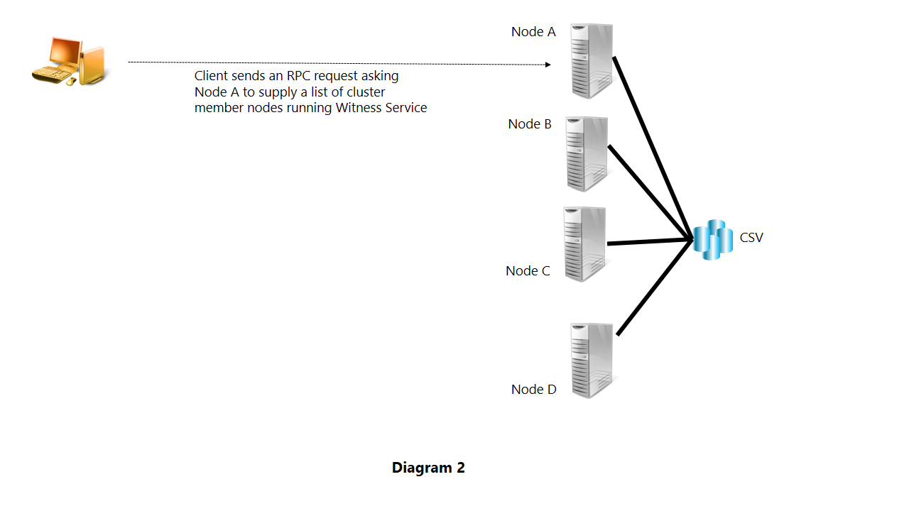
The client notices the highly available share and using the Witness Protocol (which is RPC based), requests the node to which it connected for data path access to return a list of IP addresses for each cluster node running the Witness Protocol Service. This is shown in Diagram 2.
As shown in diagram 3, the server responds with a list of IP addresses for all cluster nodes running the Witness Service Protocol. The protocol allows for returning both IPv4 and IPv6 addresses.

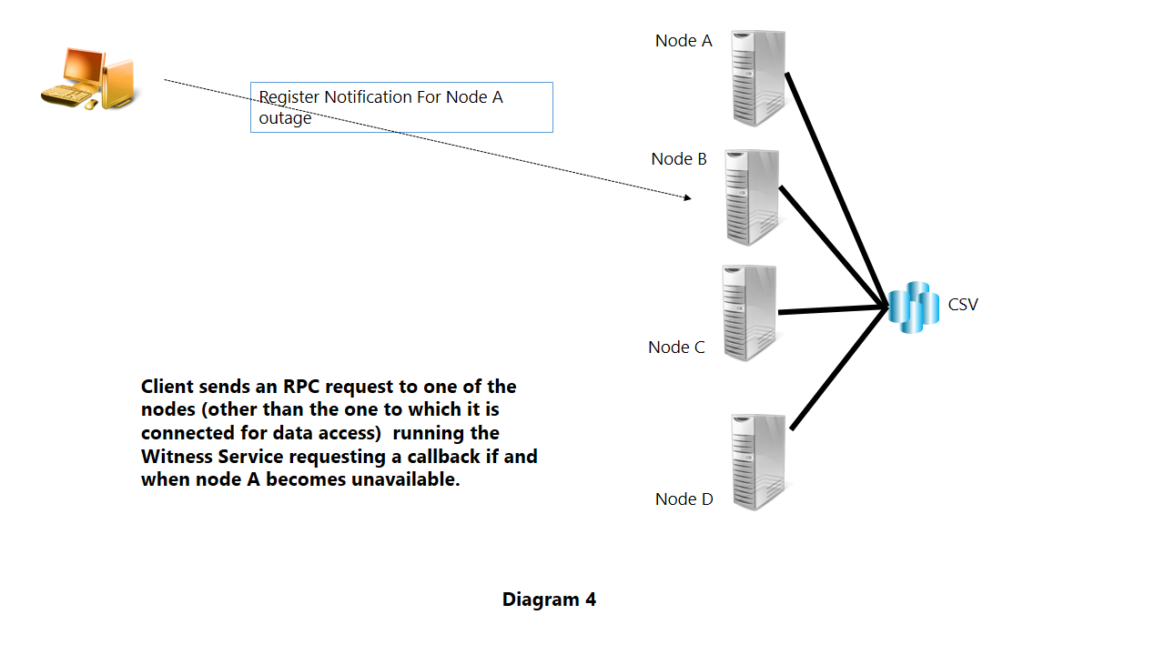
The client receives this information and registers a notification with one of the cluster nodes other than Node A, with which it is already connected to consume data via SMB 3.0. The idea is that the cluster nodes will be running a cluster quorum protocol, whatever it is, and hence the cluster nodes B, C, D (in this example) will notice if and when node A becomes unavailable. This is shown in Diagram 4.
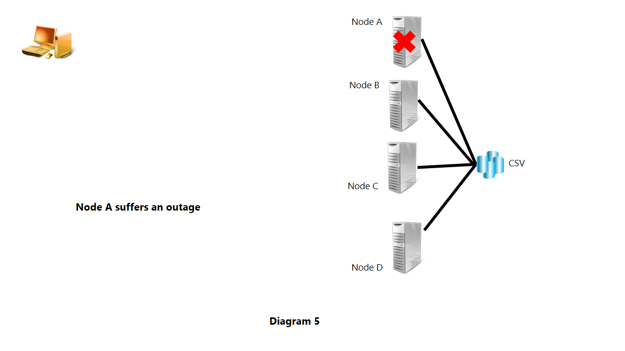
Now imagine that node A becomes unavailable for some reason as shown in Diagram 5. The exact reason is immaterial. It could be a power failure or network failure or a system crash or some other reason.
Node B (and also C and D) notice that node A is unavailable via the cluster quorum protocol running within the cluster. Node B (in this example) issues an RPC callback to the client notifying it that Node A is unavailable.

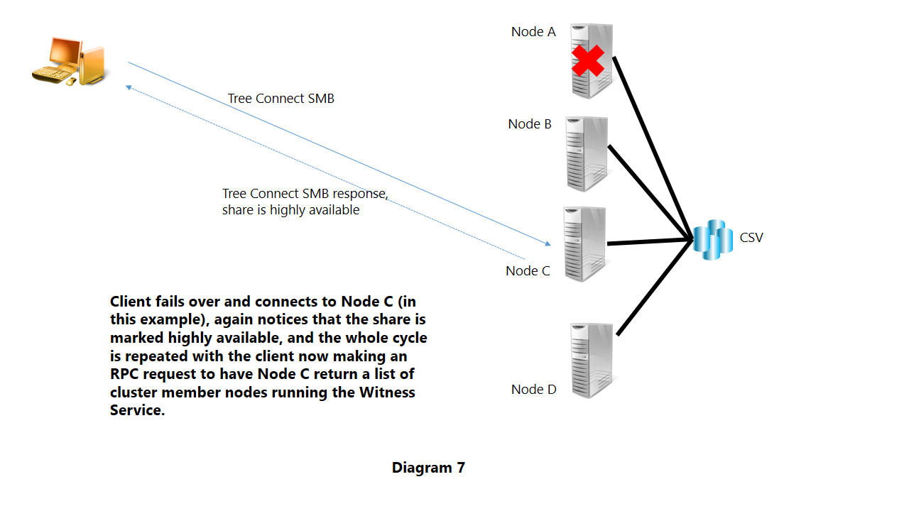
The client then performs an SMB Session Setup, Tree Connect etc to any one of the other remaining nodes. In Diagram 7 in this example, the client connected to Node C.
Note that the “client” can itself be another server e.g. the client could be a SQL server or an IIS server.
